

/image%2F3857025%2F20191105%2Fob_457303_bathroom.png)
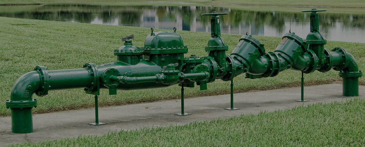
The Basics Of Backflow
Perhaps one of the most important human needs in our society is a supply of clean safe drinking water.
And it is also something that is commonly taken for granted by both the general public and also by a large number of both tradesmen and utility officials.
The number of backflow prevention devices installed improperly by both the professional plumber and the property owner or their maintenance personnel is reaching a level that is difficult to believe.
Backflow prevention devices must be installed in the proper manner so that they both can fulfil their purpose in protecting the water supply and also be tested and repaired in a safe, timely way.
They must also be protected from the elements in both warm and cold climates.
Installation requirements are just that, requirements that must be met to ensure both that the device will perform properly and also ensure the safety of the personnel that must both test and maintain the device.
There are so many factors that must be considered with each and every installation:
- Degree of hazard
- Location
- Incoming pressure
- System requirements
- Future requirements of the system
- Future hazards
The list goes on and on. In this article, we will try to cover basic installation requirements while keeping in mind that each installation is different and presents new challenges.
Being a person who works in the field both installing and testing devices I am aware of the pressure that is exerted on many plumbing contractors and utility employees by both the end-users and the property owners to both keep the installation cost as low as possible and also to keep space requirements to a minimum.
These factors are a problem in new construction and can be a nightmare in retrofit installations.
Anyone who has tried to convince a factory owner that he must spend several thousand dollars to install a device that was not required to be installed several years ago to protect the general public knows what I am talking about and if you throw in fire sprinkler systems you are really in for a fight.
Although there are many ways an installation can go wrong the most common one I have seen is the location of the device itself.
From RPZ installed in pits to DCVA installed thirty feet in the air over industrial machines, they can be a testers nightmare.
Let’s go over some basic installation requirements for the Reduced Pressure Principle Assembly [RPZ], Double Check Valve Assembly [DCVA], and both the Pressure [PVB] and Atmospheric [AVB] Vacuum Breaker.
When installing the AVB several factors must be considered, the location of the device both in relation to spill protection and the elevation of the piping and equipment being served by the device.
The AVB must be installed a minimum of six inches (check local codes) above all downstream piping and flood rims.
It must also be installed in an upright position and must never be subjected to continuous pressure for more than twelve hours.
Shutoff valves are prohibited downstream of the device.
Depending on the application the AVB can be installed in both high and low hazard applications.
The AVB only protects against back-siphonage. It provides no protection against any backpressure.
This device is probably the most commonly miss applied backflow prevention product being installed in the field today.
Plumbers find them installed below the fixture flood rim on everything from commercial garbage disposals to soap dispensers.
When installed improperly they become just another expensive elbow in the system piping.
Although this is a very simple device, the protection it provides to the potable water system when properly installed is critical to public health.
The PVB is also used to prevent back-siphonage within the water system.
This assembly while similar to the AVB can be used in many applications that require continuous pressure downstream of the device including hose reels.
Downstream shutoffs are allowed and the assembly is testable.
The PVB requires a minimum of twelve inches elevation from the critical level of the assembly to all downstream piping or equipment. It provides no protection against backpressure.
PVB must also be installed in an upright position and care must be taken as to the location of the assembly due to the possible water leakage from the assembly.
PVB is used as isolation devices in many agricultural irrigation systems in addition to many industrial applications.
As with any mechanical device, care should be taken to ensure that they are installed in such a manner that they can be tested and repaired in-line.
In colder climates, freeze protection must also be considered.
When the system requires protection against both types of backflow (back siphonage and backpressure) the system designer or installer must consider several different factors when specifying the proper assembly needed.
The degree of hazard must be the most important consideration outweighing all others in this decision.
Once the type of protection needed has been decided many other factors come into play, including space requirements, pressure loss and freeze protection just to name a few.
Whether installing assemblies for isolation (point of use) or containment (service connection) protection the same installation guidelines should always be followed.
The DCVA and DCFVA are designed to protect against both back-siphonage and backpressure in low hazard applications.
The DCVA is used in a wide range of plumbing installations on both fixtures and equipment.
It is also commonly found at the service connection providing containment protection at many low hazard buildings.
The DCFVA are usually installed on fire systems that do not contain any type of chemical additives or antifreeze.
Many of these assemblies are installed in meter pits or vaults as containment devices.
As someone who does a fair amount of device testing in the field I can say that very seldom do you find a vault that has any sort of adequate drainage provided.
Most pits have water in them and it is a common occurrence finding the backflow assembly completely submerged in several feet of stagnant water.
When you factor in the added expense for future testing and valve maintenance due to confined space requirements along with the almost impossible task of providing adequate drainage it is easy to conclude that pit or vault installations should be discouraged whenever possible.
DCVA should be installed a minimum of twelve inches and a maximum of thirty inches above the ground or floor.
These assemblies must be installed with adequate side and top clearances for both testing and maintenance.
At least twelve inches should be provided around the valve, with twenty-four inches at the test cocks. When you are installing larger assemblies greater clearances may be required.
The Reduced Pressure Principle Assembly (RPZ) and the Reduced Pressure Fire Protection Principle Assembly (RPF) are the best backflow protection the designer or installer can provide short of the physical air gap.
The RPZ and RPF protect against both backpressure and back-siphonage and can be used in low and high hazard installation.
They are installed for both points of use and containment protection.
Because these assemblies incorporate a relief port that may open to the atmosphere they should never be installed without proper drainage being assured.
RPZ and RPF as with he DCVA assemblies can present great difficulties when installing in pits or vaults.
A large assembly may require a drain line so large that it makes a pit or vault installation impossible.
An RPZ must be installed with a minimum of twenty-four inches clearance around the assembly and enough clearance above the assembly to allow for maintenance and repair.
This device should be installed at least twelve inches above the ground or floor and not more than thirty to thirty-six inches to the centre of the assembly.
When installing an RPZ a drain must be provided for the relief port.
These devices are being installed in closets, ceilings, and many other locations with no provisions being made for water spillage due to valve failure, line pressure fluctuation or any of the many reasons for relief port discharge.
The damage from these improperly installed valves can be staggering.
The solution to many of these problems is simple.
Chose the proper assembly or device needed for the protection required.
Ensure it is installed in the proper position, follow the manufacturer’s installation instructions, check your local codes, and have it tested annually.
As the ASSE motto says “Prevention Rather Than Cure” by following these few simple guidelines the public water system can be protected.


/https%3A%2F%2Fassets.over-blog.com%2Ft%2Fcedistic%2Fcamera.png)
/image%2F3857025%2F20191119%2Fob_56687a_kohler-freestanding-bath.jpg)
/image%2F3857025%2F20191119%2Fob_eef090_lighting.jpg)
/image%2F3857025%2F20191119%2Fob_657a73_water-quality.jpg)
